Awe-Inspiring Examples Of Tips About Is Voltage In A Series Circuit Divided By Loads

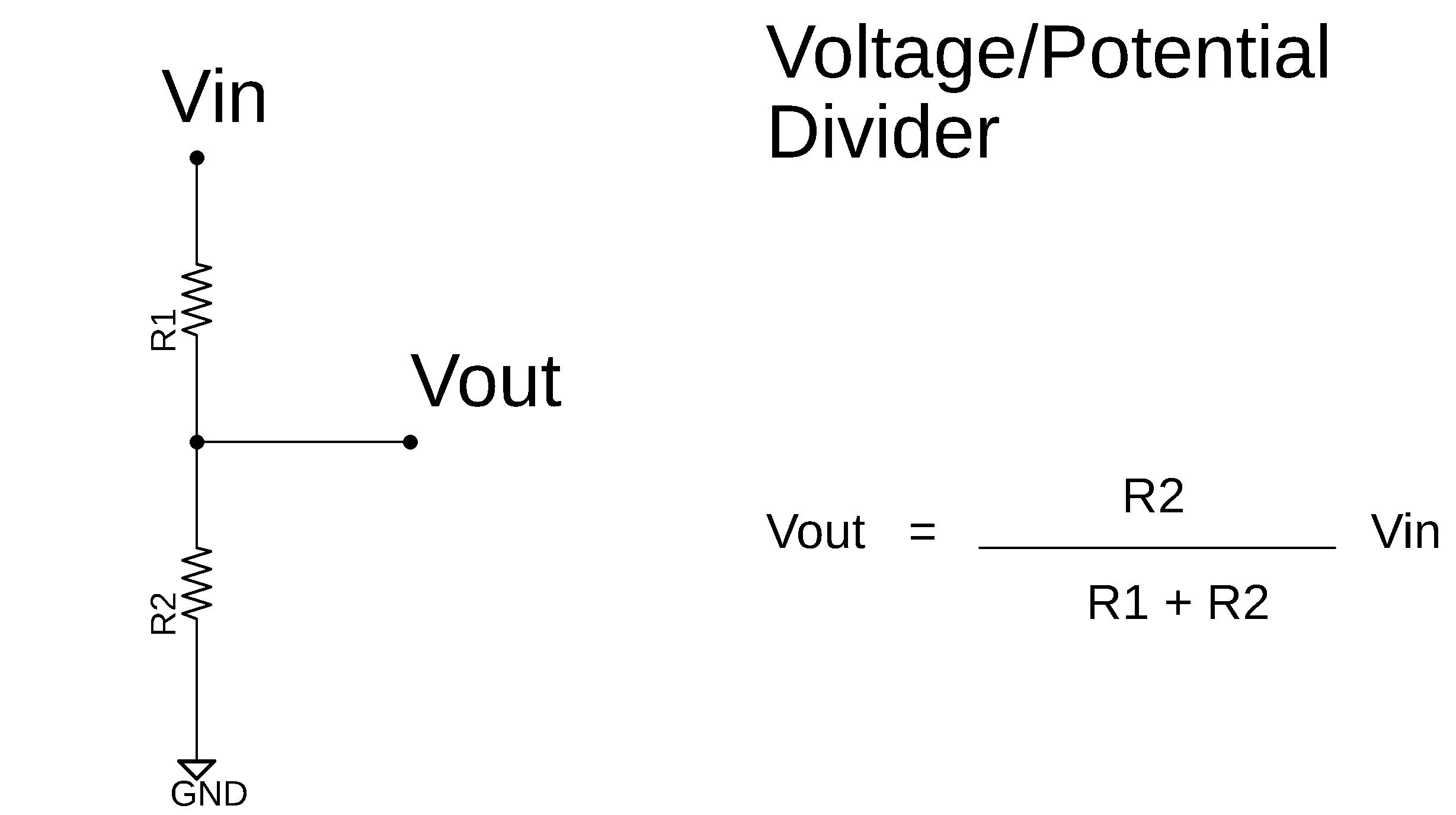
Voltage Divider Circuit Basics, Formula, Types, Applications.
Unraveling the Mystery
1. What Exactly Happens to Voltage in a Series Circuit?
Ever wondered what happens to voltage when it encounters multiple obstacles, or rather, loads, in a series circuit? It's not like it magically disappears! The truth is, voltage gets distributed, or "divided," among these loads. Think of it like sharing a pizza — each slice (load) gets a portion of the whole (voltage). If you have a very hungry crowd (high resistance), the slices might be smaller (less voltage per load). Makes sense, right?
To understand this better, imagine a simple series circuit with a battery and two resistors. The battery provides the total voltage. As the current flows through the first resistor, some of the voltage is "used up" to overcome the resistance. The remaining voltage then continues on to the next resistor, where more of it is used up. This process continues until all the voltage is consumed by the time the current returns to the battery.
The key thing to remember is that the total voltage supplied by the source is equal to the sum of the voltage drops across each load in the series circuit. You can calculate the voltage drop across each resistor using Ohm's Law: V = IR, where V is voltage, I is current, and R is resistance. So, if you know the current flowing through the circuit and the resistance of each component, you can easily figure out how the voltage is divided.
Don't worry, it's not complicated algebra. This is basic physics, designed to make our lives easier, not harder. Think of it as a waterfall cascading down rocks. Each rock (resistor) gets a little bit of the water's energy (voltage). The bigger the rock, the more energy it gets, the smaller the total energy (voltage) becomes as it nears the bottom of the cascade.

What Is A Voltage Divider Or Potential Divider, Formula And Practical Uses?
Understanding the Voltage Divider Formula
2. How to Calculate Voltage Division?
Now, let's get down to the nitty-gritty (just kidding, we're avoiding that phrase!) of calculating voltage division. There's a nifty formula that simplifies this process, called the Voltage Divider Formula. It allows you to determine the voltage across a specific resistor in a series circuit without having to calculate the current first. Pretty neat, huh?
The formula looks like this: Vx = Vtotal (Rx / Rtotal), where Vx is the voltage across resistor Rx, Vtotal is the total voltage supplied by the source, Rx is the resistance of the resistor you're interested in, and Rtotal is the total resistance of the entire series circuit. Essentially, the voltage across a resistor is directly proportional to its resistance relative to the total resistance.
Let's try an example. Suppose you have a 12V battery connected in series with a 100-ohm resistor and a 200-ohm resistor. What is the voltage drop across the 200-ohm resistor? Using the formula, V200 = 12V (200 / (100 + 200)) = 12V (200/300) = 8V. Therefore, the voltage across the 200-ohm resistor is 8V. The voltage across the 100-ohm resistor would therefore be 4V, adding up to the total 12V supplied.
Remember, the bigger the resistance, the larger the slice of the voltage "pizza" it gets. This principle is used in countless electronic circuits, from simple volume controls to complex voltage regulation circuits. So, understanding voltage division is crucial for anyone dabbling in electronics or electrical engineering. Think of it like this: it's the secret sauce to understanding how electronics actually work!
Resistance and its Role in Voltage Distribution
3. How Does Resistance Affect Voltage Division?
Resistance plays a starring role in voltage division. It's the key determinant of how the voltage is distributed amongst the different loads in the series circuit. A higher resistance means a larger share of the voltage drop, while a lower resistance means a smaller share. It's all about proportion and balance!
If you have two resistors in series and one has a much higher resistance than the other, almost all the voltage will be dropped across the larger resistor. This can be useful in circuits where you need to significantly reduce the voltage before it reaches a sensitive component. The resistor acts like a gatekeeper, controlling how much voltage passes through it.
On the flip side, if you have two resistors with very similar resistance values, the voltage will be divided almost equally between them. This is often used in circuits where you need to create a reference voltage that is a fraction of the supply voltage. It's like splitting the check evenly with a friend after a delicious meal! Each contributes equally.
Consider this: If a series circuit has a short circuit (very low resistance) across one of the components, almost no voltage will be dropped across it. Instead, nearly all the voltage will be dropped across the remaining components. This is why short circuits are dangerous — they can cause excessive current flow and damage components. Understanding resistance helps us design safer and more efficient circuits.
Practical Applications of Voltage Division
4. Where Can You See Voltage Division in Action?
Voltage division isn't just a theoretical concept; it's used everywhere in electronics! From adjusting the volume on your stereo to controlling the brightness of your phone screen, voltage division is working behind the scenes. It's a fundamental principle that makes countless electronic devices possible.
One common application is in potentiometer circuits, which are used as volume controls and dimmers. A potentiometer is essentially a variable resistor, allowing you to adjust the resistance and therefore the voltage drop across different parts of the circuit. By turning a knob, you're effectively changing the ratio of resistances, and thus the voltage applied to the speaker or light.
Another crucial application is in sensor circuits. Many sensors, like temperature sensors and light sensors, produce a change in resistance in response to a change in the environment. By placing these sensors in a voltage divider circuit, you can convert the change in resistance into a change in voltage, which can then be measured and interpreted by a microcontroller or other electronic system.
Voltage dividers are also used in bias circuits for transistors. Transistors need a specific voltage applied to their base (or gate) in order to operate correctly. A voltage divider can be used to create this bias voltage, ensuring that the transistor operates in the desired region. So, the next time you're using your favorite electronic gadget, remember that voltage division is likely playing a role in its functionality!
Troubleshooting Voltage Division Issues
5. What Happens When Voltage Division Goes Wrong?
Even with the best designs, things can sometimes go wrong with voltage dividers. Understanding common issues and how to troubleshoot them can save you a lot of headaches, and perhaps, prevent fried circuits! So, let's dive into some potential problems.
One of the most frequent problems is a faulty resistor. Resistors can drift in value over time, or they can be damaged by excessive current or voltage. If a resistor in a voltage divider circuit changes its resistance value, the voltage division will be affected, leading to unexpected behavior in the circuit. You can usually spot this by using a multimeter to measure the resistance of each resistor and comparing it to its specified value.
Another potential issue is an open circuit. If one of the resistors in the voltage divider circuit is completely open (meaning the resistance is infinite), no current will flow through the circuit, and the voltage across all the other components will be zero. This is usually easy to diagnose with a multimeter, as you'll see no voltage across the faulty resistor.
Finally, sometimes the load connected to the voltage divider can affect its performance. If the load has a very low resistance, it can "load down" the voltage divider, meaning it draws too much current and reduces the voltage across the divider. To avoid this, make sure the load resistance is significantly higher than the resistance of the voltage divider itself. By carefully checking each component and considering the load, you can usually track down and fix most voltage division problems.
FAQ: Voltage Division in Series Circuits
6. Q: What is the main principle behind voltage division in a series circuit?
A: The main principle is that the total voltage supplied by the source is divided among the resistors (loads) in proportion to their resistance. Higher resistance gets a larger share of the voltage.
7. Q: How can I calculate the voltage across a specific resistor in a series circuit without measuring it?
A: You can use the Voltage Divider Formula: Vx = Vtotal (Rx / Rtotal), where Vx is the voltage across the resistor Rx, Vtotal is the total voltage, and Rtotal is the total resistance of the series circuit.
8. Q
A: If a resistor opens, the circuit will break and no current will flow. If the resistor value changes significantly, it will affect the voltage division, potentially causing unexpected behavior in the circuit or preventing the circuit from working at all. You need to test the resistors using multimeter to make sure it will work as desired.

Current Calculation In A Series Circuit Mastering The Basics Electricove

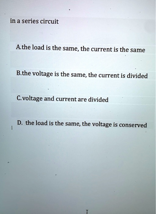
SOLVED In A Series Circuit A. The Load Is Same; Current

How To Calculate Electric Resistance
